
Technical
What Is A PLC Made Of? Basic PLC Hardware Guide
The rapid transformation of intelligent industrial automation has created a surge in market demands for new control engineering positions in manufacturing industries centralized around the use of the PLC, or programmable logic controller.
PLC is the gold standard for industrial process control technology. The key benefit of a PLC over a hard-wired relay system is the ease of which one can make changes to the programmable control logic.
This article exposes you to the details of PLC hardware and modules that form a PLC control system. If you are an aspiring industrial automation student, understanding the basic architecture and operation of a PLC is your first step in mastering this technology for your future career. For diligent educators, you can use this as a quick, easy-to-read handout to introduce your students to the concept of PLCs in their first class.
Key points:
- The most basic PLC hardware components include processor, I/O modules, power supply, communication interface, and programming devices. Thus we can think of a PLC as a industrial computer, designed for control stability under harsh conditions.
- In terms of programming language, each PLC manufacture (such as Siemens, Allen-Bradley) has their own programming software suite specific to their product. To ensure consistent programming protocol, however, an international standard was established.
PLC hardware architecture
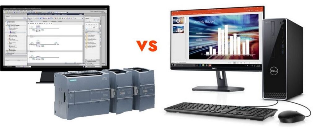
We can think of PLC as a personal computer designed especially for use in the control of a vast array of manufacturing machines and industrial automation systems.
The hardware of a PLCs consists of:

1. Processor
Similar to a PC, the CPU is the brain of a PLC. It contains the microprocessors monitoring the PLC program, the memory storage, and data transfer with I/O modules. It replaces the traditional timers, relays, and counters.
More specifically, the CPU interprets the input signals and execute the control actions according to the program stored in its memory, communicating the decisions as action signals to the outputs.
A PLC can be integrated with two different types of processors: single bit processor for logic functions, and word processor for processing text and numerical data, and managing and recording data.
The memory unit stores the user’s PLC programs. These are control logic instructions that will be executed by the CPU. It also contains all input data for processing and the outputs.
Internal random-access memory (RAM) can be divided into two categories:
- Program memory: stores the user PLC program. It occupies the largest portion of total memory usage.
- Storage memory: store critical data required for program execution such as inputs and outputs status, register values, timer & counter, and so on.
Internal read-only memory (ROM): can only be read from, i.e. no user input is allowed. This unit stores the permanent PLC critical system program. The system program is the first program executed when PLC is turned on. This program test and ensure the integrity of I/O devices and other miscellaneous devices on the PLC system. The software located in ROM is called firmware.
External PLC’s memory: Similar to a USB or portable hard drive in a PC, this is an optional memory that can be connected to the PLC’s CPU. If internal memory already has a good backup battery for emergency power supply, external memory is not required.
2. Input and output modules:
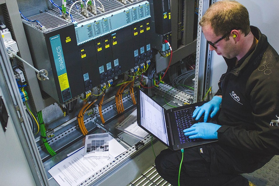
The input and output (I/O) modules provide the physical interface between the PLC processor and the real-world field devices.
The inputs can be triggered switches or sensor data; the outputs can be controlled instructions to motors, pumps, valves, and so on. There are various kinds of modules to control different types of sensors and actuators but they all share common features: removable terminal blocks, isolation, and diagnostic indicators. These features enable the PLC to be efficient in maintenance tasks, internal protection, and troubleshooting.
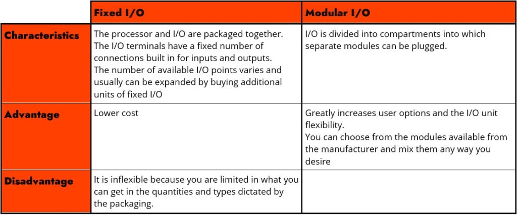
There are two ways in which I/Os can be incorporated into the PLC: fixed and modular.
Input and output devices can be categorized as giving signals that are discrete, digital or analog. Therefore, the standard and most common I/O modules are:
- Digital input modules: receive discrete signals from the input devices and convert them appropriately for further processing, while electrically isolating them before being transferred to the memory.
- Digital output modules: transfer the results of the logical processing of an automation program to the output devices. The results of the program execution are logic signals that should be altered into power signals inside the digital output module, capable of energizing the corresponding output devices.
- Analog input modules: contain all the necessary circuits for the connection of analog signals and their corresponding alteration into digital ones
- Analog output modules: receive numerical data in digital form from the central processing unit of the PLC, transforming them into an analog voltage or current, in order to control the operation of an analog device.
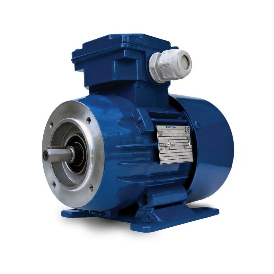
Typical digital devices are monitors, PCs. Typical analog devices are small motors, servo valves, DC servo motors, drivers for high power motors with varying speeds of rotation, analog instruments, etc.
3. Power supply
The power supply unit converts the main AC voltage to low DC voltage suitable for delicate processors and internal circuits in the I/O interface modules.
Most PLC functions on a 24V DC supply. For a small/micro PLC system, this power supply can be used to also power field devices. For a larger system, however, field devices are powered by external AC or DC supplies.
PLC has a lithium battery that provides contingency power to RAM. In case of a power failure, this power allows RAM to save the PLC program. Some PLCs also even have a capacitor to ensure power to the RAM while the battery is disconnected or being replaced.
4. Communication interface
The communications interface is used to receive and transmit data on communications networks from or to other remote PLCs. This includes data communication protocols, human-machine interfaces (HMI) and hard-wired control panels, operator mimic screens, and so on.
5. Programming device
The programming device is a computer installed with programming software, which enables you to enter and download desired programs into the PLC processor’s memory, or to edit existing programs. These can be a PC, a laptop, or even an inexpensive compact hand-held computer for easy troubleshooting equipment.
More specifically:
- Handheld programming devices will normally contain enough memory to allow the unit to retain programs while being carried from one place to another.
- Desktop consoles are likely to have a visual display unit with a full keyboard and screen display.
- Personal computers are widely used for programming PLCs. A major advantage of using a computer is that the program can be stored on a hard disk or a CD and copies easily made. The computer is connected to the PLC by Ethernet or serial interfaces, such as RS-232, RS-485 or RS-422.
PLC programs are first designed and verified via specific programming software, then they are transferred to the memory unit for deployment.
PLC programming software
Similar to Windows, Mac, and Linux operating systems for a PC, each PLC manufacturer has a specific programming software to configure their own PLCs.
For example, SIEMENS has SIMATIC STEP 7, Allen Bradley has the RSLogix series, Mitsubishi has GX Developer, and so on.
To ensure consistency in PLC programming languages amongst various manufacturers, the International Electrotechnical Commission (IEC) established the international programming standard IEC 61131-3.
For any students learning about PLC, automation, or instrumentation control, understanding different PLC programming languages and knowing how to command them with competency within the scope of IEC 61131-3 is one of the fundamental career skills.
PART 3 (COMING SOON)
Bibliography
IDC Technologies, Fundamentals of Instrumentation, Process Control, PLCs and SCADA for Plant Operators and Other Non-Instrument Personnel, 5th ed. IDC Technologies, 2011.
Related news:

Industry report
How To Stay Ahead Of The Automation Trend? – An Industry Research
Automated labor is inevitable. Learn how industrial automation is changing the job landscape and training...
Learn more
Technical
What Is PLC? Simple PLC Concepts Explained
PLC or Programmable Logic Controller is the building block of industrial automation. Quickly learn simple...
Learn more